
Page 118 - Air and gas Drilling Field Guide 3rd Edition
P. 118
5.5 Compressor Shaft Power Requirements 109
compressors have few moving parts. The main disadvantages are as follow: (1)
cannot adjust to flow line back pressures (fixed compression ratios), (2) need fre-
quent specific maintenance of rotating wear surfaces to prevent slippage, (3)
most rotary compressors operate with oil lubrication in the compression cham-
bers, and (4) can only be used as primary compressors [1, 2, 7].
5.5 COMPRESSOR SHAFT POWER REQUIREMENTS
The most important single factor affecting the successful outcome of air and gas
drilling operations is the availability of constant, reliable volumetric flow rates of
air or gas to the well. This must be the case even when significant (and frequent)
changes in back pressure occur during these operations. The only two compres-
sor subclasses that can meet these flexibility requirements are the reciprocating
compressor and the rotary compressor. In what follows, the important calcula-
tion techniques that allow for the proper evaluation and selection of the appro-
priate compressors for air and gas drilling operations are reviewed [1, 7, 10].
This section derives the theoretical power required at the compressor shaft to
compress the gas in the compressor.
5.5.1 Basic Single-Stage Shaft Power Requirement
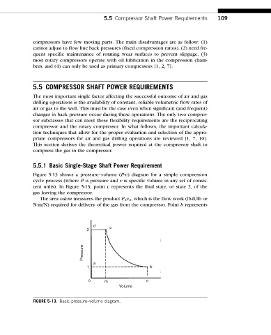
Figure 5-13 shows a pressure–volume (P-v) diagram for a simple compression
cycle process (where P is pressure and v is specific volume in any set of consis-
tent units). In Figure 5-13, point c represents the final state, or state 2, of the
gas leaving the compressor.
The area odcm measures the product P 2 v 2 , which is the flow work (lb-ft/lb or
N-m/N) required for delivery of the gas from the compressor. Point b represents
d c
2
Pressure
a
1 b
o m n
Volume
FIGURE 5-13. Basic pressure–volume diagram.