
Page 122 - Air and gas Drilling Field Guide 3rd Edition
P. 122
5.5 Compressor Shaft Power Requirements 113
_ w
Q 1 ¼ ¼ _ w n 1 (5-28)
g 1
Therefore, Equation (5-27) can be rewritten as
k 1
2 3
k P 2 k
6 7
_ W s ¼ P 1 Q 14 15: (5-29)
k 1 P 1
This expression is valid for a single-stage compressor and for any set of consis-
tent units. With Equation (5-29), the shaft power to compress a continuous flow
rate of gas can be determined knowing properties of the gas (specifically k),
the initial pressure and volumetric flow rate of the gas entering the compressor
(state 1), and the exit pressure of gas exiting the compressor (state 2).
5.5.2 Multistage Shaft Power Requirements
Using Equation (5-24), the minimum shaft power required for a multistage com-
pressor can be derived [10]. Equation (5-24) can be used for each stage of a mul-
tistage compressor and added together for the total shaft work required by the
compressor. Such an expression can be minimized to obtain the conditions for
minimum shaft work for a multistage compressor. Minimum shaft work is attained
when a multistage compressor is designed with equal compression ratios for each
stage and with intercoolers that cool the gas entering each stage to a temperature
that is nearly the same as the temperature entering the first stage of the compres-
sor [10]. Once these conditions are obtained for the multistage compressor, the
expression for the shaft power can be obtained in the same manner as given in
Equations (5-25) to (5-29).
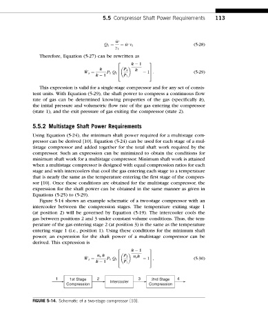
Figure 5-14 shows an example schematic of a two-stage compressor with an
intercooler between the compression stages. The temperature exiting stage 1
(at position 2) will be governed by Equation (5-19). The intercooler cools the
gas between positions 2 and 3 under constant volume conditions. Thus, the tem-
perature of the gas entering stage 2 (at position 3) is the same as the temperature
entering stage 1 (i.e., position 1). Using these conditions for the minimum shaft
power, an expression for the shaft power of a multistage compressor can be
derived. This expression is
k 1
2 3
n s k P 2 n s k
6 7
_ W s ¼ P 1 Q 14 15; (5-30)
k 1 P 1
1 1st Stage 2 Intercooler 3 2nd Stage 4
Compression Compression
FIGURE 5-14. Schematic of a two-stage compressor [10].