
Page 113 - Air and gas Drilling Field Guide 3rd Edition
P. 113
104 CHAPTER 5 Compressors and Nitrogen Generators
The bottom pressure versus volumetric flow rate plot in Figure 5-9 shows the
typical situation when the back pressure on the outlet side of the compressor is
less than the built-in design output pressure. Under these conditions, the gas exit-
ing the compressor expands in the expansion tank and the initial portion of the
pipeline until the pressure is equal to the pipeline back pressure [1].
Rotary compressors can also be designed with two stages. Such compressors
are designed with nearly equal compression ratios for each stage (i.e., minimum
input power requirements). Thus, because the volumetric flow rate (in actual
cfm) is reduced from one stage to the next, the volume displacement of each
stage (its geometric size) is progressively smaller.
Rotary compressors are only used as primary compressors in drilling
operations.
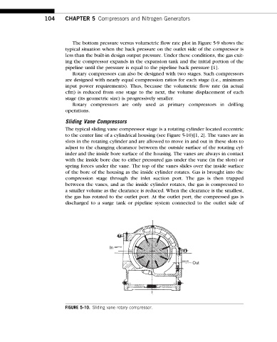
Sliding Vane Compressors
The typical sliding vane compressor stage is a rotating cylinder located eccentric
to the center line of a cylindrical housing (see Figure 5-10)[1, 2]. The vanes are in
slots in the rotating cylinder and are allowed to move in and out in these slots to
adjust to the changing clearance between the outside surface of the rotating cyl-
inder and the inside bore surface of the housing. The vanes are always in contact
with the inside bore due to either pressured gas under the vane (in the slots) or
spring forces under the vane. The top of the vanes slides over the inside surface
of the bore of the housing as the inside cylinder rotates. Gas is brought into the
compression stage through the inlet suction port. The gas is then trapped
between the vanes, and as the inside cylinder rotates, the gas is compressed to
a smaller volume as the clearance is reduced. When the clearance is the smallest,
the gas has rotated to the outlet port. At the outlet port, the compressed gas is
discharged to a surge tank or pipeline system connected to the outlet side of
In
Out
FIGURE 5-10. Sliding vane rotary compressor.