
Page 182 - Air and gas Drilling Field Guide 3rd Edition
P. 182
7.2 General Derivation 173
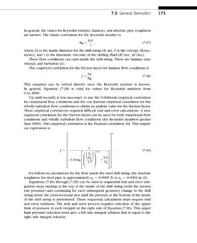
In general, the values for Reynolds number, diameter, and absolute pipe roughness
are known. The classic correlation for the Reynolds number is
D i V
N R ¼ ; (7-27)
n
where D i is the inside diameter for the drill string (ft, m), V is the velocity (ft/sec,
2 2
m/sec), and n is the kinematic viscosity of the drilling fluid (ft /sec, m /sec).
Three flow conditions can exist inside the drill string. These are laminar, tran-
sitional, and turbulent [1].
The empirical correlation for the friction factor for laminar flow conditions is
64
f ¼ N R : (7-28)
This equation can be solved directly once the Reynolds number is known.
In general, Equation (7-28) is valid for values for Reynolds numbers from
0 to 2000.
Up until recently it was necessary to use the Colebrook empirical correlation
for transitional flow conditions and the von Karman empirical correlation for the
wholly turbulent flow conditions to obtain an analytic value for the friction factor.
These empirical correlations required difficult trial and error calculations. A new
empirical correlation for the friction factor can be used for both transitional flow
conditions and wholly turbulent flow conditions (for Reynolds numbers greater
than 2000). This empirical correlation is the Haaland correlation [6]. This empiri-
cal expression is
2
2 3
6 7
6 7
6 7
6 7
6 7
1
6 7
f ¼ 6 7 : (7-29)
2
1 1:11 3
6 0 7
e p
6 7
6 7 7
6
B C
6 D p 6:9 7 7
6
6 B C þ 7 7
1:8 log6
@ 3:7 A
4 N R 5 5
4
For follow-on calculations for the flow inside the steel drill string, the absolute
roughness for steel pipe is approximately e p ¼ 0.0005 ft or e p ¼ 0.0002 m [1].
Equations (7-26) through (7-29) can be used in sequential trial and error inte-
gration steps starting at the top of the inside of the drill string (with the known
exit pressure) and continuing for each subsequent geometry change in the drill
string inside the cross-sectional area until the pressure at the bottom of the inside
of the drill string is determined. These sequential calculation steps require trial
and error solutions. The trial and error process requires selection of the upper
limit of pressure in each integral on the right side of Equation (7-26). This upper
limit pressure selection must give a left side integral solution that is equal to the
right side integral solution.