
Page 186 - Air and gas Drilling Field Guide 3rd Edition
P. 186
7.3 Aerated Fluid Drilling Model 177
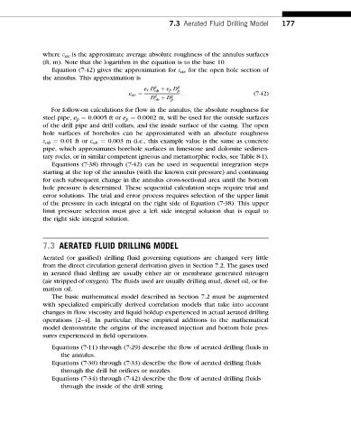
where e av is the approximate average absolute roughness of the annulus surfaces
(ft, m). Note that the logarithm in the equation is to the base 10.
Equation (7-42) gives the approximation for e av for the open hole section of
the annulus. This approximation is
e r D 2 oh þ e p D 2 p
e av ¼ : (7-42)
D 2 þ D 2
oh p
For follow-on calculations for flow in the annulus, the absolute roughness for
steel pipe, e p ¼ 0.0005 ft or e p ¼ 0.0002 m, will be used for the outside surfaces
of the drill pipe and drill collars, and the inside surface of the casing. The open
hole surfaces of boreholes can be approximated with an absolute roughness
e oh ¼ 0.01 ft or e oh ¼ 0.003 m (i.e., this example value is the same as concrete
pipe, which approximates borehole surfaces in limestone and dolomite sedimen-
tary rocks, or in similar competent igneous and metamorphic rocks, see Table 8-1).
Equations (7-38) through (7-42) can be used in sequential integration steps
starting at the top of the annulus (with the known exit pressure) and continuing
for each subsequent change in the annulus cross-sectional area until the bottom
hole pressure is determined. These sequential calculation steps require trial and
error solutions. The trial and error process requires selection of the upper limit
of the pressure in each integral on the right side of Equation (7-38). This upper
limit pressure selection must give a left side integral solution that is equal to
the right side integral solution.
7.3 AERATED FLUID DRILLING MODEL
Aerated (or gasified) drilling fluid governing equations are changed very little
from the direct circulation general derivation given in Section 7.2. The gases used
in aerated fluid drilling are usually either air or membrane generated nitrogen
(air stripped of oxygen). The fluids used are usually drilling mud, diesel oil, or for-
mation oil.
The basic mathematical model described in Section 7.2 must be augmented
with specialized empirically derived correlation models that take into account
changes in flow viscosity and liquid holdup experienced in actual aerated drilling
operations [2–4]. In particular, these empirical additions to the mathematical
model demonstrate the origins of the increased injection and bottom hole pres-
sures experienced in field operations.
Equations (7-11) through (7-29) describe the flow of aerated drilling fluids in
the annulus.
Equations (7-30) through (7-33) describe the flow of aerated drilling fluids
through the drill bit orifices or nozzles.
Equations (7-34) through (7-42) describe the flow of aerated drilling fluids
through the inside of the drill string.