Page 251 - Air and gas Drilling Field Guide 3rd Edition
P. 251

242     CHAPTER 9 Aerated Fluids Drilling


                                                        Pressure (psia)
                                         0    500  1000  1500  2000  2500  3000  3500
                                     –7000
                                                                                 –2200
                                     –7500
                                               Injection Pressure
                                                                                 –2400
                                     –8000
                                    Depth (ft)  –8500  Bottom Hole Pressure      –2600  Depth (m)


                                     –9000
                                                                                 –2800
                                     –9500

                                                                                 –3000
                                    –10000
                                         0     400   800   1200  1600  2000   2400
                                                     Pressure (N/cm 2  abs)


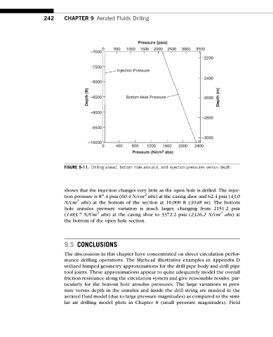
                          FIGURE 9-11. Drilling ahead, bottom hole annulus, and injection pressures versus depth.


                          shows that the injection changes very little as the open hole is drilled. The injec-
                                                          2
                          tion pressure is 87.4 psia (60.4 N/cm abs) at the casing shoe and 62.4 psia (43.0
                               2
                          N/cm abs) at the bottom of the section at 10,000 ft (3048 m). The bottom
                          hole annulus pressure variation is much larger, changing from 2151.2 psia
                                       2
                                                                                        2
                          (1483.7 N/Cm abs) at the casing shoe to 3372.2 psia (2326.2 N/cm abs)at
                          the bottom of the open hole section.


                          9.5 CONCLUSIONS
                          The discussions in this chapter have concentrated on direct circulation perfor-
                          mance drilling operations. The Mathcad illustrative examples in Appendix D
                          utilized lumped geometry approximations for the drill pipe body and drill pipe
                          tool joints. These approximations appear to quite adequately model the overall
                          friction resistance along the circulation system and give reasonable results, par-
                          ticularly for the bottom hole annulus pressures. The large variations in pres-
                          sure versus depth in the annulus and inside the drill string are masked in the
                          aeratedfluid model(duetolarge pressure magnitudes)ascomparedtothe simi-
                          lar air drilling model plots in Chapter 8 (small pressure magnitudes). Field
   246   247   248   249   250   251   252   253   254   255   256