
Page 60 - Air and gas Drilling Field Guide 3rd Edition
P. 60
3.3 Wellhead Equipment 51
Packer Inserts
Bore of Top
Quick-Release
Access Flaps Top
Outer Cylinder
Lock-Down
Locking Grooves
in Body
Packer
Vent
Donut
Opening Side of
Pusher Plate
Piston
Closing Side of
Piston
Opening Closing Hydraulic Ports
Hydraulic Ports
SD 203-03
Operating Piston
Vent
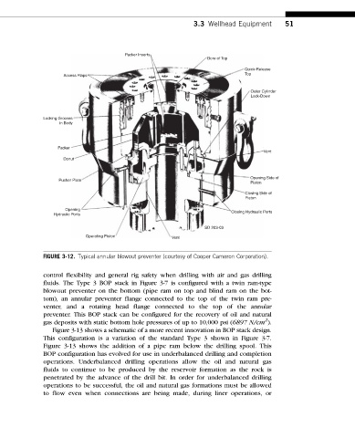
FIGURE 3-12. Typical annular blowout preventer (courtesy of Cooper Cameron Corporation).
control flexibility and general rig safety when drilling with air and gas drilling
fluids. The Type 3 BOP stack in Figure 3-7 is configured with a twin ram-type
blowout preventer on the bottom (pipe ram on top and blind ram on the bot-
tom), an annular preventer flange connected to the top of the twin ram pre-
venter, and a rotating head flange connected to the top of the annular
preventer. This BOP stack can be configured for the recovery of oil and natural
2
gas deposits with static bottom hole pressures of up to 10,000 psi (6897 N/cm ).
Figure 3-13 shows a schematic of a more recent innovation in BOP stack design.
This configuration is a variation of the standard Type 3 shown in Figure 3-7.
Figure 3-13 shows the addition of a pipe ram below the drilling spool. This
BOP configuration has evolved for use in underbalanced drilling and completion
operations. Underbalanced drilling operations allow the oil and natural gas
fluids to continue to be produced by the reservoir formation as the rock is
penetrated by the advance of the drill bit. In order for underbalanced drilling
operations to be successful, the oil and natural gas formations must be allowed
to flow even when connections are being made, during liner operations, or