
Page 63 - Air and gas Drilling Field Guide 3rd Edition
P. 63
54 CHAPTER 3 Surface Equipment
3.4.2 Burn Pit
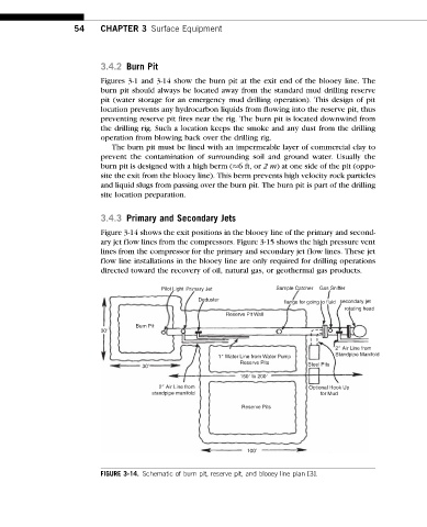
Figures 3-1 and 3-14 show the burn pit at the exit end of the blooey line. The
burn pit should always be located away from the standard mud drilling reserve
pit (water storage for an emergency mud drilling operation). This design of pit
location prevents any hydrocarbon liquids from flowing into the reserve pit, thus
preventing reserve pit fires near the rig. The burn pit is located downwind from
the drilling rig. Such a location keeps the smoke and any dust from the drilling
operation from blowing back over the drilling rig.
The burn pit must be lined with an impermeable layer of commercial clay to
prevent the contamination of surrounding soil and ground water. Usually the
burn pit is designed with a high berm ( 6 ft, or 2m) at one side of the pit (oppo-
site the exit from the blooey line). This berm prevents high velocity rock particles
and liquid slugs from passing over the burn pit. The burn pit is part of the drilling
site location preparation.
3.4.3 Primary and Secondary Jets
Figure 3-14 shows the exit positions in the blooey line of the primary and second-
ary jet flow lines from the compressors. Figure 3-15 shows the high pressure vent
lines from the compressor for the primary and secondary jet flow lines. These jet
flow line installations in the blooey line are only required for drilling operations
directed toward the recovery of oil, natural gas, or geothermal gas products.
Pilot Light Primary Jet Sample Catcher Gas Sniffer
Deduster
flange for going to fluid secondary jet
rotating head
Reserve Pit Wall
Burn Pit
30
2 Air Line from
1 Water Line from Water Pump Standpipe Manifold
Reserve Pits
30 Steel Pits
150 to 200
2 Air Line from Optional Hook Up
standpipe manifold for Mud
Reserve Pits
100
FIGURE 3-14. Schematic of burn pit, reserve pit, and blooey line plan [3].