
Page 61 - Air and gas Drilling Field Guide 3rd Edition
P. 61
52 CHAPTER 3 Surface Equipment
Rotating Control Head
Flow Line to Shale Shaker
(used when not flow drilling)
Annular Preventer
Pipe Rams
Blind Rams
Choke Line
Pipe Rams
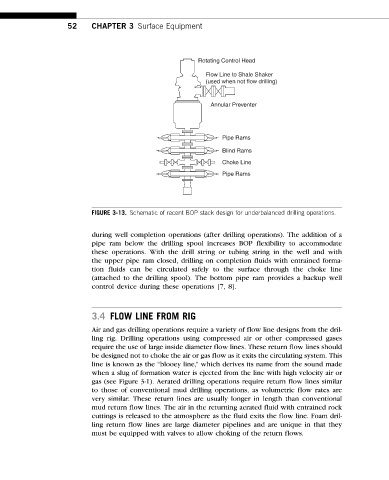
FIGURE 3-13. Schematic of recent BOP stack design for underbalanced drilling operations.
during well completion operations (after drilling operations). The addition of a
pipe ram below the drilling spool increases BOP flexibility to accommodate
these operations. With the drill string or tubing string in the well and with
the upper pipe ram closed, drilling on completion fluids with entrained forma-
tion fluids can be circulated safely to the surface through the choke line
(attached to the drilling spool). The bottom pipe ram provides a backup well
control device during these operations [7, 8].
3.4 FLOW LINE FROM RIG
Air and gas drilling operations require a variety of flow line designs from the dril-
ling rig. Drilling operations using compressed air or other compressed gases
require the use of large inside diameter flow lines. These return flow lines should
be designed not to choke the air or gas flow as it exits the circulating system. This
line is known as the “blooey line,” which derives its name from the sound made
when a slug of formation water is ejected from the line with high velocity air or
gas (see Figure 3-1). Aerated drilling operations require return flow lines similar
to those of conventional mud drilling operations, as volumetric flow rates are
very similar. These return lines are usually longer in length than conventional
mud return flow lines. The air in the returning aerated fluid with entrained rock
cuttings is released to the atmosphere as the fluid exits the flow line. Foam dril-
ling return flow lines are large diameter pipelines and are unique in that they
must be equipped with valves to allow choking of the return flows.