
Page 65 - Air and gas Drilling Field Guide 3rd Edition
P. 65
56 CHAPTER 3 Surface Equipment
Angle Iron
Inside Blooey Line
Air Flow
2" Nipple
Sample Discharge 2" unior
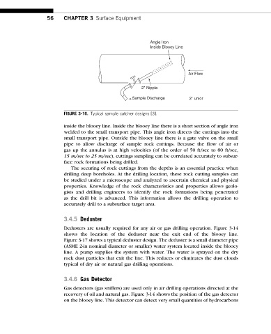
FIGURE 3-16. Typical sample catcher designs [3].
inside the blooey line. Inside the blooey line there is a short section of angle iron
welded to the small transport pipe. This angle iron directs the cuttings into the
small transport pipe. Outside the blooey line there is a gate valve on the small
pipe to allow discharge of sample rock cuttings. Because the flow of air or
gas up the annulus is at high velocities (of the order of 50 ft/sec to 80 ft/sec,
15 m/sec to 25 m/sec), cuttings sampling can be correlated accurately to subsur-
face rock formations being drilled.
The securing of rock cuttings from the depths is an essential practice when
drilling deep boreholes. At the drilling location, these rock cutting samples can
be studied under a microscope and analyzed to ascertain chemical and physical
properties. Knowledge of the rock characteristics and properties allows geolo-
gists and drilling engineers to identify the rock formations being penetrated
as the drill bit is advanced. This information allows the drilling operation to
accurately drill to a subsurface target area.
3.4.5 Deduster
Dedusters are usually required for any air or gas drilling operation. Figure 3-14
shows the location of the deduster near the exit end of the blooey line.
Figure 3-17 shows a typical deduster design. The deduster is a small diameter pipe
(ASME 2-in nominal diameter or smaller) water system located inside the blooey
line. A pump supplies the system with water. The water is sprayed on the dry
rock dust particles that exit the line. This reduces or eliminates the dust clouds
typical of dry air or natural gas drilling operations.
3.4.6 Gas Detector
Gas detectors (gas sniffers) are used only in air drilling operations directed at the
recovery of oil and natural gas. Figure 3-14 shows the position of the gas detector
on the blooey line. This detector can detect very small quantities of hydrocarbons