
Page 64 - Air and gas Drilling Field Guide 3rd Edition
P. 64
3.4 Flow Line from Rig 55
Booster Compressors
Soap Pump Mist Unit
Valve Manifold
Optional
Standpipe Flowmeter
To Secondary Jet To Primary Jet
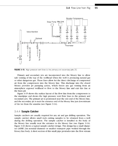
FIGURE 3-15. High pressure vent lines to the primary and secondary jets [3].
Primary and secondary jets are incorporated into the blooey line to allow
safe venting of the top of the wellhead when the well is producing natural gas
or other dangerous gas. These lines allow for the direct discharge of compressed
air from the compressors into the blooey line. This discharge into the closed
blooey provides jet pumping action, which forces any gas venting from an
atmosphere exposed wellhead to flow to the blooey line and exit this line at
the burn pit.
Figure 3-15 shows the surface layout of the flow line from the compressors to
the standpipe and shows the high pressure vent flow lines to the primary and
secondary jets. The primary jet is positioned near the exit end of the blooey line,
and the secondary jet is near the entrance end of the blooey line just downstream
of the tee from the annulus (see Figure 3-14).
3.4.4 Sample Catcher
Sample catchers are usually required for any air and gas drilling operation. The
sample catcher allows small rock cutting samples to be obtained from a well
during the drilling operation. The sample catcher is installed in the body of
the blooey line usually near the entrance to the blooey line (see Figure 3-14).
Figure 3-16 shows a typical sample catcher design. This design has a small diame-
ter (ASME 2-in nominal diameter or smaller) transport pipe welded through the
blooey line body. A short section of this small pipe protrudes into the flow stream