
Page 104 - Aircraft Stuctures for Engineering Student
P. 104
88 Energy methods of structural analysis
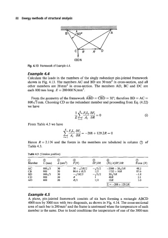
Fig. 4.1 3 Framework of Example 4.4.
Example 4.4
Calculate the loads in the members of the singly redundant pin-jointed framework
shown in Fig. 4.13. The members AC and BD are 30 mm2 in cross-section, and all
other members are 20mm2 in cross-section. The members AD, BC and DC are
each 800 mm long. E = 200 000 N/mm2.
From the geometry of the framework AFD = CTD = 30"; therefore BD = AC =
800fimm. Choosing CD as the redundant member and proceeding from Eq. (4.22)
we have
Le FiLi aFi
--=
E Ai dR 0
i= 1
From Table 4.3 we have
- -268 + 129.2R = 0
i= 1
Hence R = 2.1 N and the forces in the members are tabulated in column 0 of
Table 4.3.
Table 4.3 (Tension positive)
0 0 0 @ 0 @ 0
Member L(mm) A(m2) F(N) 6'FIaR (FL/A)aF/aR Force (N)
AC 800J3 30 50 - J3R/2 -J3/3/2 -2000 + 20J3R 48.2
CB 800 20 86.6 + R/2 112 1732 + 10R 87.6
BD 800J3 30 -J3R/2 -J3/3/2 20J3R -1.8
CD 800 20 R 1 40R 2.1
AD 800 20 RI2 112 IOR 1 .o
C = -268 + 129.2R
Example 4.5
A plane, pin-jointed framework consists of six bars forming a rectangle ABCD
4000 mm by 3000 mm with two diagonals, as shown in Fig. 4.14. The cross-sectional
area of each bar is 200 mm2 and the frame is unstressed when the temperature of each
member is the same. Due to local conditions the temperature of one of the 3000 mm