
Page 107 - Aircraft Stuctures for Engineering Student
P. 107
4.7 Solution of statically indeterminate systems 91
loads in addition to direct loads. It is usual, however, except for the thin-walled
structures in Part I1 of this book, to ignore deflections produced by shear forces.
We only consider, therefore, bending and direct force contributions to the internal
complementary energy of such structures. The method of analysis is illustrated in
the following example.
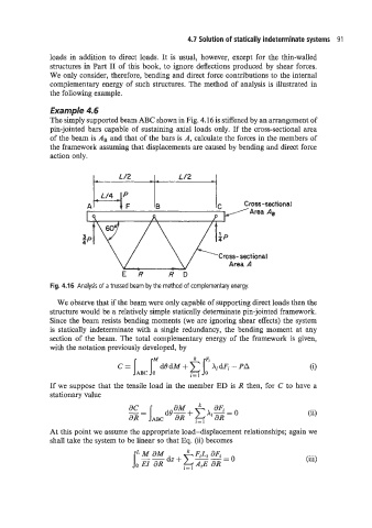
Example 4.6
The simply supported beam ABC shown in Fig. 4.16 is stiffened by an arrangement of
pin-jointed bars capable of sustaining axial loads only. If the cross-sectional area
of the beam is AB and that of the bars is A, calculate the forces in the members of
the framework assuming that displacements are caused by bending and direct force
action only.
L /2 -- L/2
Cross- sectional
E R R D
Fig. 4.16 Analysis of a trussed beam by the method of complementary energy.
We observe that if the beam were only capable of supporting direct loads then the
structure would be a relatively simple statically determinate pin-jointed framework.
Since the beam resists bending moments (we are ignoring shear effects) the system
is statically indeterminate with a single redundancy, the bending moment at any
section of the beam. The total complementary energy of the framework is given,
with the notation previously developed, by
If we suppose that the tensile load in the member ED is R then, for C to have a
stationary value
(ii)
At this point we assume the appropriate load-displacement relationships; again we
shall take the system to be linear so that Eq. (ii) becomes
li FiLi 3Fi
(iii)
2=1