
Page 106 - Aircraft Stuctures for Engineering Student
P. 106
90 Energy methods of structural analysis
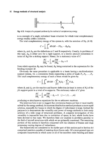
Fig. 4.15 Analysis of a propped cantilever by the method of complementary energy.
is an example of a singly redundant beam structure for which total complementary
energy readily yields a solution.
The total complementary energy of the system is, with the notation of Eq. (4.18)
c = jL IrdOdM - PAC - RBAB
where Ac and AB are the deflections at C and B respectively. Usually, in problems of
this type, AB is either zero for a rigid support, or a known amount (sometimes in
terms of RB) for a sinking support. Hence, for a stationary value of C
from which equation RB may be found; RB being contained in the expression for the
bending moment M.
Obviously the same procedure is applicable to a beam having a multiredundant
support system, viz. a continuous beam supporting a series of loads P1, Pz, . . . , P,,.
The total complementary energy of such a beam would be given by
where Rj and A, are the reaction and known deflection (at least in terms of Rj) of the
jth support point in a total of m supports. The stationary value of C gives
producing m simultaneous equations for the m unknown reactions.
The intention here is not to suggest that continuous beams are best or most readily
solved by the energy method; the moment distribution method produces a more rapid
solution, especially for beams in which the degree of redundancy is large. Instead the
purpose is to demonstrate the versatility and power of energy methods in their ready
solution of a wide range of structural problems. A complete investigation of this
versatility is impossible here due to restriction of space; in fact, whole books have
been devoted to this topic. We therefore limit our analysis to problems peculiar to
the field of aircraft structures with which we are primarily concerned. The remaining
portion of this section is therefore concerned with the solution of frames and rings
possessing varying degrees of redundancy.
The frameworks we considered in the earlier part of this section and in Section 4.6
comprised members capable of resisting direct forces only. Of a more general type are
composite frameworks in which some or all of the members resist bending and shear