
Page 404 - Aircraft Stuctures for Engineering Student
P. 404
10.3 Wings 385
section in which G varies from wall to wall, Eq. (10.23) takes the form
de 1 r ds
This equation may be rewritten as
(10.25)
in which GREF is a convenient reference value of the shear modulus. Equation (10.25)
is now rewritten as
dB 1 ds
-
-- (10.26)
dz ~ARGREF +R 't'
in which the modulus-weighted thickness t* is given by
(10.27)
Then, in Eq. (10.24), 6 becomes Jds/t*.
Example 10.7
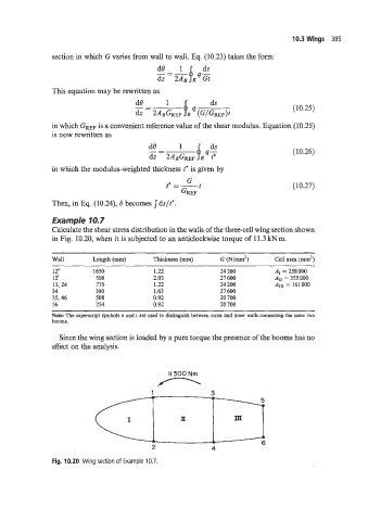
Calculate the shear stress distribution in the walls of the three-cell wing section shown
in Fig. 10.20, when it is subjected to an anticlockwise torque of ll.3kNm.
Wall Length (mm) Thickness (mm) G (Nlmm2) area (mm2)
12: 1650 1.22 24 200 AI = 258 000
12' 508 2.03 27 600 ,411 = 355000
13,24 775 1.22 24 200 A111 = 161 000
34 380 1.63 27 600
35,46 508 0.92 20 700
56 254 0.92 20 700
Note: The superscript symbols o and i are used to distinguish between outer and inner walls connecting the same two
booms.
Since the wing section is loaded by a pure torque the presence of the booms has no
effect on the analysis.
n
II 300 Nm
Fig. 10.20 Wing section of Example 10.7.