
Page 405 - Aircraft Stuctures for Engineering Student
P. 405
386 Stress analysis of aircraft components
Choosing GREF = 27 600N/mm2 then, from Eq. (10.27)
24 200
tip = -
x 1.22 = 1.07mm
27 600
Similarly
tf3 = r;4 = 1.07mm, t& = ti6 = t& = 0.69mm
Hence
Similarly
61zi = 250, 613 = 6% = 725, 634 233, 635 = 646 = 736, b56 = 368
Substituting the appropriate values of 6 in Eq. (10.24) for each cell in turn gives the
following.
For cell I
For cell I1
de
_- 1 [-250qI + qII(250 + 725 + 233 + 725) - 233q11~]
dz - 2 x 355 OOOGREF (ii)
For cell 111
d6’ 1
233
-= [-233q11+ q111(736 i- + 736 + 368)] (iii)
dz 2 x 161 OOOGREF
In addition, from Eq. (10.22)
11.3 x lo6 = 2(258 OOOqI + 355 OOOqII + 161 OOO~III) (3
Solving Eqs (i) to (iv) simultaneously gives
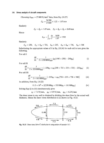
qr = 7.1N/mm, qIr = 8.9N/mm, qIII = 4.2N/mm
The shear stress in any wall is obtained by dividing the shear flow by the actual wall
thickness. Hence the shear stress distribution is as shown in Fig. 10.21.
Fig. 10.21 Shear stress (Wrnm’) distribution in wing section of Example 10.7.