
Page 406 - Aircraft Stuctures for Engineering Student
P. 406
10.3 Wings 387
10.3.3 Shear
-I_I*iilPIUI_..Y_-------~~.--~--~ . I---
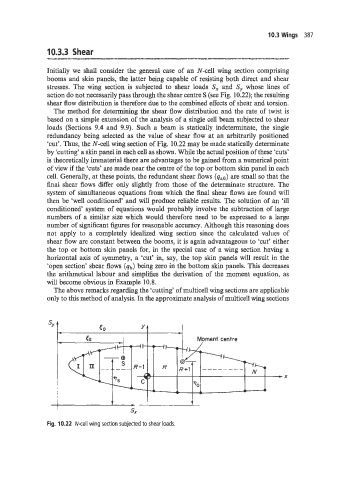
Initially we shall consider the general case of an N-cell wing section comprising
booms and skin panels, the latter being capable of resisting both direct and shear
stresses. The wing section is subjected to shear loads S, and S, whose lines of
action do not necessarily pass through the shear centre S (see Fig. 10.22); the resulting
shear flow distribution is therefore due to the combined effects of shear and torsion.
The method for determining the shear flow distribution and the rate of twist is
based on a simple extension of the analysis of a single cell beam subjected to shear
loads (Sections 9.4 and 9.9). Such a beam is statically indeterminate, the single
redundancy being selected as the value of shear flow at an arbitrarily positioned
‘cut’. Thus, the N-cell wing section of Fig. 10.22 may be made statically determinate
by ‘cutting’ a skin panel in each cell as shown. While the actual position of these ‘cuts’
is theoretically immaterial there are advantages to be gained from a numerical point
of view if the ‘cuts’ are made near the centre of the top or bottom skin panel in each
cell. Generally, at these points, the redundant shear flows are small so that the
final shear flows differ only slightly from those of the determinate structure. The
system of simultaneous equations from which the final shear flows are found will
then be ‘well conditioned’ and will produce reliable results. The solution of an ‘ill
conditioned’ system of equations would probably involve the subtraction of large
numbers of a similar size which would therefore need to be expressed to a large
number of significant figures for reasonable accuracy. Although this reasoning does
not apply to a completely idealized wing section since the calculated values of
shear flow are constant between the booms, it is again advantageous to ‘cut’ either
the top or bottom skin panels for, in the special case of a wing section having a
horizontal axis of symmetry, a ‘cut’ in, say, the top skin panels will result in the
‘open section’ shear flows (qb) being zero in the bottom skin panels. This decreases
the arithmetical labour and simplifies the derivation of the moment equation, as
will become obvious in Example 10.8.
The above remarks regarding the ‘cutting’ of multicell wing sections are applicable
only to this method of analysis. In the approximate analysis of multicell wing sections
ES Moment centre
I- = = :I
\
-x
70
- A e
1 -
*
I t I t
s,
Fig. 10.22 N-cell wing section subjected to shear loads.