
Page 407 - Aircraft Stuctures for Engineering Student
P. 407
388 Stress analysis of aircraft components
&
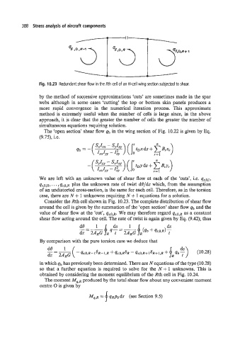
Fig. 10.23 Redundant shear flow in the Rth cell of an N-cell wing section subjected to shear.
by the method of successive approximations ‘cuts’ are sometimes made in the spar
webs although in some cases ‘cutting’ the top or bottom skin panels produces a
more rapid convergence in the numerical iteration process. This approximate
method is extremely useful when the number of cells is large since, in the above
approach, it is clear that the greater the number of cells the greater the number of
simultaneous equations requiring solution.
The ‘open section’ shear flow qb in the wing section of Fig. 10.22 is given by Eq.
(9.75), i.e.
We are left with an unknown value of shear flow at each of the ‘cuts’, i.e. qs,o,I,
qs,o,II, . . . , qs,O,N plus the unknown rate of twist de/& which, from the assumption
of an undistorted cross-section, is the same for each cell. Therefore, as in the torsion
case, there are N + 1 unknowns requiring N + 1 equations for a solution.
Consider the Rth cell shown in Fig. 10.23. The complete distribution of shear flow
around the cell is given by the summation of the ‘open section’ shear flow qb and the
value of shear flow at the ‘cut’, qs,O,R. We may therefore regard qs,O,R as a constant
shear flow acting around the cell. The rate of twist is again given by Eq. (9.42); thus
By comparison with the pure torsion case we deduce that
in which qb has previously been determined. There are N equations of the type (10.28)
so that a further equation is required to solve for the N + 1 unknowns. This is
obtained by considering the moment equilibrium of the Rth cell in Fig. 10.24.
The moment Mq,R produced by the total shear flow about any convenient moment
centre 0 is given by
M~,R = f qRp0 ds (see Section 9.5)