
Page 413 - Aircraft Stuctures for Engineering Student
P. 413
394 Stress analysis of aircraft components
From column @
6
P,,r = 764.4 N
r=l
From column @
From column @
c P y:r ( =-43680Nmm
r
r= I
From Eqs (10.15)
Sx,w = 0, Sy,w = 10 x lo3 - 764.4 = 9235.6N
Also, since Cx is an axis of symmetry, I,, = 0 and Eq. (9.75) for the ‘open section’
shear flow reduces to
or
9235’6 cBryr = -2.715 x 10-42Bryr
qb = - 34.02 x lo6 r=l r= 1
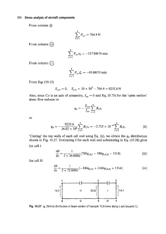
‘Cutting’ the top walls of each cell and using Eq. (ii), we obtain the qb distribution
shown in Fig. 10.27. Evaluating 6 for each wall and substituting in Eq. (10.28) gives
for cell I
6 0 5 0 4
Fig. 10.27 qb (Wmrn) distribution in beam section of Example 10.9 (view along z axis towards C).