
Page 418 - Aircraft Stuctures for Engineering Student
P. 418
10.3 Wings 399
Table 10.6
Cell I Cell 11 Cell I11
CS 0.129 0.149 0.112 0.121
Assumed q (N/mm) 288 367 155
coq 51.38 37.15 18.76 41.10
coq 5.20 6.63 4.97 2.10
coq 0.93 0.67 0.25 0.56
coq 0.09 0.12 0.07 0.03
Final q (N/mm) 345.6 435.6 198.8
2Aq (Nmm) 1.78 x 10' 3.09 x 10' 0.64 x 10'
Total T (Nmm) 5.51 x IO*
Actual q (N/mm) 7.1 8.9 4.1
(T= 11.3kNm)
10.3.7 Method of successive approximations - shear
l*lm"l...-. __1_1_ I"----.--. -..*ll*.l-...-*
The method is restricted to shear loads applied through the shear centre of the wing
section so that the rate of twist in each cell is zero. Having determined the position of
the shear centre from the resulting shear flow distribution, the case of a wing section
subjected to shear loads not applied through the shear centre is solved by replacing
the actual loading system by shear loads acting through the shear centre together
with a pure torque; the two separate solutions are then superimposed.
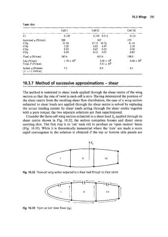
Consider the three-cell wing section subjected to a shear load S, applied through its
shear centre shown in Fig. 10.32; the section comprises booms and direct stress
carrying skin. The lirst step is to 'cut' each cell to produce an 'open section' beam
(Fig. 10.33). While it is theoretically immaterial where the 'cuts' are made a more
rapid convergence in the solution is obtained if the top or bottom skin panels are
t sv
Fig. 10.32 Three-cell wing section subjected to a shear load through its shear centre.
Fig. 10.33 'Open section'shear flows (qt,).