
Page 420 - Aircraft Stuctures for Engineering Student
P. 420
10.3 Wings 401
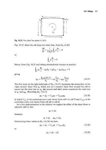
Fig. 10.35 Final shear flow system in Cell II.
Fig. 10.35. Since the cell does not twist then, from Eq. (9.42)
dB 1 ds
-=- q-=o
dz 2AIIGf11 t
or
Hence, from Fig. 10.35 and taking anticlockwise torques as positive
ds
fII qb 7 - qI1611 + qIbI,II f ~III~III.11 = 0
giving
(10.37)
The first term on the right-hand side of Eq. (10.37) represents the proportion of the
'open section' shear flow qb which acts as a constant shear flow around the cell to
cancel out the twist due to qb; the second and third terms counteract the twist due
to qr and qllI. Rewriting Eq. (10.37)
411 = QiI + C1,rrqr + CI1I:lIqIII (10.38)
in which CIqII is the correction carry over factor from cell I to cell I1 and CIIIqII is the
correction carry over factor from cell 111 to cell 11.
As a first approximation in the solution we neglect the effect of the shear flows in
adjacent cells so that
411 = 41
Similarly
41 = rlf? qIII = 4h
Substituting these values in Eq. (10.38) we have
(10.39)
or
411 = 41 + 41 (10.40)