
Page 423 - Aircraft Stuctures for Engineering Student
P. 423
404 Stress analysis of aircraft components
Table 10.7
~ ~
cell I Cell I1 Cell I11
I qb wt 12 166.0 6945.7 -6218.9
6 1128.7 1870.0 2013.6
cs 0.08 0.134 0.086 0.093
6[= -(I4bW)/4 -10.78 -3.71 3.09
coq -0.50 -0.86 0.29 -0.32
coq -0.08 -0.04 -0.03 -0.05
coq -0.01 -0.01 0 0
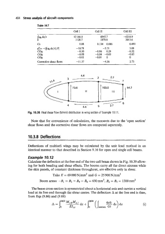
Corrective shear flows -11.37 -4.36 2.73
I 54.7
Fig. 10.38 Final shear flow (N/mm) distribution in wing section of Example 10.1 1.
Note that for convenience of calculation, the moments due to the ‘open section’
shear flows and the corrective shear flows are computed separately.
10.3.8 Deflections
Deflections .of multicell wings may be calculated by the unit load method in an
identical manner to that described in Section 9.10 for open and single cell beams.
Example 10.12
Calculate the deflection at the free end of the two-cell beam shown in Fig. 10.39 allow-
ing for both bending and shear effects. The booms carry all the direct stresses while
the skin panels, of constant thickness throughout, are effective only in shear.
Take E = 69 000 N/mm2 and G = 25 900 N/mm2
2
Boom areas: -B, = B3 = B4 = B6 = 650mm , B2 = B5 = 1300mm2
The beam cross-section is symmetrical about a horizontal axis and carries a vertical
load at its free end through the shear centre. The deflection A at the free end is then,
from Eqs (9.86) and (9.88)