
Page 426 - Aircraft Stuctures for Engineering Student
P. 426
10.4 Fuselage frames and wing ribs 407
H
(a) (b)
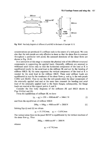
Fig. 10.41 Free body diagrams of stiffeners JK and HKD in the beam of Example 10.13.
concentrations are produced if a stiffener ends in the centre of a web panel. We note
also that the web panels are only effective in shear so that the shear flow is constant
throughout a particular web panel; the assumed directions of the shear flows are
shown in Fig. 10.40.
It is instructive at this stage to examine the physical role of the different structural
components in supporting the applied loads. Generally, stiffeners are assumed to
withstand axial forces only so that the horizontal component of the load at K is
equilibrated locally by the axial load in the stiffener JK and not by the bending of
stiffener HKD. By the same argument the vertical component of the load at K is
resisted by the axial load in the stiffener HKD. These axial stiffener loads are
equilibrated in turn by the resultants of the shear flows q1 and q2 in the web panels
CDKJ and JKHG. Thus we see that the web panels resist the shear component of
the externally applied load and at the same time transmit the bending and axial
load of the externally applied load to the beam flanges; subsequently, the flange
loads are reacted at the support points A and E.
Consider the free body diagrams of the stiffeners JK and HKD shown in
Figs 10.41(a) and (b).
From the equilibrium of stiffener JK we have
(ql - q2) x 250 = 4000 sin 60" = 3464.1 N (i)
and from the equilibrium of stiffener HKD
200q1 + 100q2 = 4000 COS 60" = 2000 N (ii)
Solving Eqs (i) and (ii) we obtain
q1 = 11.3 N/mm, q2 = -2.6 N/mm
The vertical shear force in the panel BCGF is equilibrated by the vertical resultant of
the shear flow q3. Thus
3ooq3 = 4000 COS 60" = 2000 N
whence
q3 = 6.7N/mm