Page 428 - Aircraft Stuctures for Engineering Student
P. 428

10.4 Fuselage frames and wing ribs  409

                      10325 N


                                                       2825 N
                                       Tension


                                              6.7   -      11.3  -  D
                         A     23.3
                                                                    Shear flows in Wrnm
                           -                         G      2.6  ,,
                               23.3
                                              6.7
                                        F


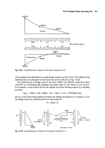
                Fig. 10.43  Load distributions in flanges of the beam of  Example 10.13.


                The complete load distribution in each flange is shown in Fig. 10.43. The stiffener load
                distributions are calculated in the same way and are shown in Fig. 10.44.
                  The distribution of  flange load in the bays ABFE and BCGF could have been
                obtained by considering the bending and axial loads on the beam at any section.
                For example, at the section AE we can replace the actual loading system by a bending
                moment

                       MAE = 5000 x 250 + 2000 x 750 - 3464.1 x 50 = 2 576 800 N IIUII
                and an axial load acting midway between the flanges (irrespective of whether or not
                the flange areas are symmetrical about this point) of
                                              P = 3464.1 N


                                                                3464 N
                       6.7
                                                 11.3
                                                                                2260 N
                                                J    J     r      K    K
                                                           2.6


                     E                                                   H
                              (Tension)                    Shear flows in Nlmm
                Fig. 10.44  Load distributions in stiffeners of the beam of Example 10.13.
   423   424   425   426   427   428   429   430   431   432   433