
Page 424 - Aircraft Stuctures for Engineering Student
P. 424
10.3 Wings 405
2mm
3 1
mm
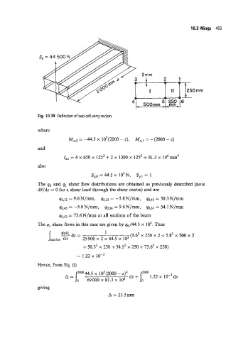
Fig. 10.39 Deflection of two-cell wing section.
where
M,,~ = -44.5 x 10³(2000 - z), M,,~ = 42000 - Z)
and
I,, = 4 x 650 x 1252 + 2 x 1300 x 1252 = 81.3 x 106mm4
also
sy,o = 44.5 x io3 N, sy,l = 1
The qo and q1 shear flow distributions are obtained as previously described (note
de/& = 0 for a shear load through the shear centre) and are
q0,12 = 9.6N/mm, 40.23 = -5.8N/mm, qO,43 = 50.3N/mm
40~45 = -5.8N/mm, 40.56 = 9.6N/m, = 54.1 N/m
qo.52 = 73.6N/mm at all sections of the beam
The q1 shear flows in this case are given by q0/44.5 x lo3. Thus
4041 1
ds
- = (9A2 x 250 x 2 + 5.g2 x 500 x 2
S section Gt 25900 x 2 x 44.5 x lo3
+ 50.32 x 250 + 54.12 x 250 + 73.6’ x 250)
= 1.22
Hence, from Eq. (i)
200044.5 103(2000 - z)~ + J,’” 1.22 x dz
dz
69000 x 81.3 x lo6
giving
A = 23.5mm