
Page 421 - Aircraft Stuctures for Engineering Student
P. 421
402 Stress analysis of aircraft components
Similarly and simultaneously, corrections qy and dII are applied to the approxima-
tions for qI and qIII which in turn affect qII. Thus, when the corrective shear flows
become negligibly small we have
Similar expressions are derived for qI and qIII.
Example 10. I I
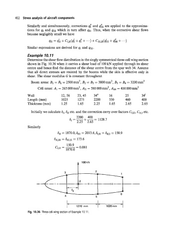
Determine the shear flow distribution in the singly symmetrical three-cell wing section
shown in Fig. 10.36 when it carries a shear load of 100 kN applied through its shear
centre and hence find the distance of the shear centre from the spar web 34. Assume
that all direct stresses are resisted by the booms while the skin is effective only in
shear. The shear modulus G is constant throughout
2
2
Boom areas: B1 = B6 = 2500mm , B2 = B5 = 3800mm B3 = B4 = 3200mm2
Cell areas: AI = 265 000 mm2, A11 = 580 000 m2, AIII = 410 000 mm2
Wall 12, 56 23,45 34" 16 25 34'
Length (mm) 1025 1275 2200 330 460 400
Thickness (mm) 1.25 1.65 2.25 1.65 2.65 2.65
Initially we calculate SI, SI, etc. and the correction carry over factors CI,II, CII,I etc.
SI=-+-= 2200 400 1128.7
2.25 2.65
Similarly
t IOokN
n I 7
L
6
1270 rnrn 1020 rnrn
Fig. 10.36 Three-cell wing section of Example 10.1 1.