
Page 422 - Aircraft Stuctures for Engineering Student
P. 422
10.3 Wings 403
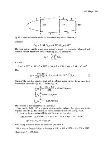
Fig. 10.37 Open section shear flow (N/mm) distribution in wing section of Example 10.1 1.
Similarly
CII,I = 0.134, CII,JII = 0.086, CIII~II = 0.093
The wing section has the x axis as an axis of symmetry, is completely idealized and
carries a vertical shear load only so that Eq. (10.35) reduces to
in which
Z, = 2 x 2500 x 1652 + 2 x 3800 x 2302 + 2 x 3200 x 2002 = 7.94 x 10’ mm4
Thus
-100 x io3 I2
C B,Y, = - 1 .26 x 10-~ BJI,
qb = 7.94 x 10⁸ r=l
r=l
‘Cutting’ the top skin panel in each cell, we obtain, using Eq. (i), the qb shear flow
distribution shown in Fig. 10.37. From Fig. 10.37
qb 7 = 2.65 = 12 166.0N/mm
ds
tII qb 7 = 6945.7 N/mm
ds
$11, qb 7 = -6218.9 N/mm
The solution is now completed in Table 10.7.
Note that in Table 10.7 a negative sign is used to indicate that 4 etc. are in the
opposite sense to qb. The final shear flow distribution is shown in Fig. 10.38.
A check on the vertical equilibrium of the wing section gives
(1 1.4 x 400 + 73.6 x 400 + 2 x 4.4 x 30 + 103.0 x 460 + 2 x 2.7 x 65
+54.7 x 330)/103 = lOOkN
Now taking moments about the centre of spar web 34
100 x lo3& = 2AIqI + 2AIIqIl+ 2A111qI11f 110.1 x 460 x 1270 + 52 x 330 x 2290
which gives Es = 946.8 mm.