
Page 427 - Aircraft Stuctures for Engineering Student
P. 427
408 Stress analysis of aircraft components
C
G
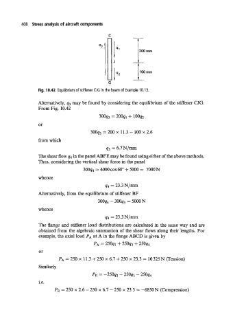
Fig. 10.42 Equilibrium of stiffener CJG in the beam of Example 10.13.
Alternatively, q3 may be found by considering the equilibrium of the stiffener CJG.
From Fig. 10.42
3ooq3 = 200ql + looqz
or
3ooq3 = 200 X 11.3 - 100 X 2.6
from which
43 = 6.7N/=
The shear flow q4 in the panel ABFE may be found using either of the above methods.
Thus, considering the vertical shear force in the panel
3ooq4 = 4000 COS 60" + 5000 = 7000 N
whence
44 = 23.3 N/m
Alternatively, from the equilibrium of stiffener BF
3OOq4 - 3OOq3 = 5OOON
whence
44 = 23.3 N/m
The flange and stiffener load distributions are calculated in the same way and are
obtained from the algebraic summation of the shear flows along their lengths. For
example, the axial load PA at A in the flange ABCD is given by
PA = 250ql + 25oq3 + 25oq4
or
PA = 250 x 11.3 + 250 x 6.7 + 250 x 23.3 = 10 325N (Tension)
Similarly
PE = -250q2 - 25093 - 25oq4
i.e.
PE = 250 x 2.6 - 250 x 6.7 - 250 x 23.3 = -6850N (Compression)