
Page 429 - Aircraft Stuctures for Engineering Student
P. 429
410 Stress analysis of aircraft components
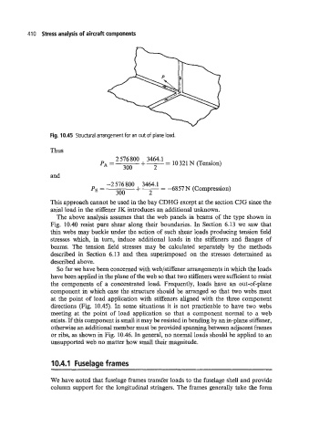
Fig. 10.45 Structural arrangement for an out of plane load.
Thus
576
PA = +-- 3464'1 - 10 321 N (Tension)
300 2
and
+--
-2 576 800 3464.1
PE = - -6857 N (Compression)
300 2
This approach cannot be used in the bay CDHG except at the section CJG since the
axial load in the stiffener JK introduces an additional unknown.
The above analysis assumes that the web panels in beams of the type shown in
Fig. 10.40 resist pure shear along their boundaries. In Section 6.13 we saw that
thin webs may buckle under the action of such shear loads producing tension field
stresses which, in turn, induce additional loads in the stiffeners and flanges of
beams. The tension field stresses may be calculated separately by the methods
described in Section 6.13 and then superimposed on the stresses determined as
described above.
So far we have been concerned with web/stiffener arrangements in which the loads
have been applied in the plane of the web so that two stiffeners were sufficient to resist
the components of a concentrated load. Frequently, loads have an out-of-plane
component in which case the structure should be arranged so that two webs meet
at the point of load application with stiffeners aligned with the three component
directions (Fig. 10.45). In some situations it is not practicable to have two webs
meeting at the point of load application so that a component normal to a web
exists. If this component is small it may be resisted in bending by an in-plane stiffener,
otherwise an additional member must be provided spanning between adjacent frames
or ribs, as shown in Fig. 10.46. In general, no normal loads should be applied to an
unsupported web no matter how small their magnitude.
10.4.1 Fuselage frames
We have noted that fuselage frames transfer loads to the fuselage shell and provide
column support for the longitudinal stringers. The frames generally take the form