
Page 434 - Aircraft Stuctures for Engineering Student
P. 434
10.5 Cut-outs in wings and fuselages 41 5
15000N I
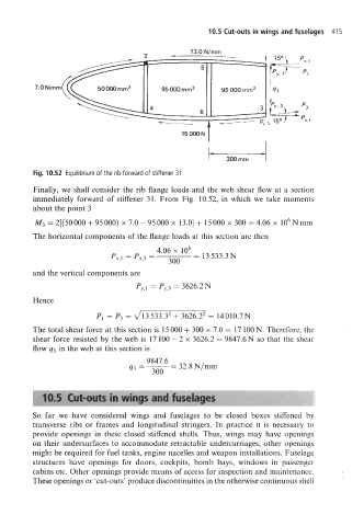
Fig. 10.52 Equilibrium of the rib forward of stiffener 31.
Finally, we shall consider the rib flange loads and the web shear flow at a section
immediately forward of stiffener 31. From Fig. 10.52, in which we take moments
about the point 3
M3=2[(50000+95000) x7.0-95000~ 13.0]+15000x300=4.06x 10⁶Nmm
The horizontal components of the flange loads at this section are then
4.06 x lo6
PX,l = px,3 = = 13 533.3N
300
and the vertical components are
Py,l = Py,3 = 3626.2N
Hence
PI = P3 = J13 533.32 + 3626.22 = 14010.7N
The total shear force at this section is 15 000 + 300 x 7.0 = 17 100 N. Therefore, the
shear force resisted by the web is 17 100 - 2 x 3626.2 = 9847.6N so that the shear
flow g3 in the web at this section is
9847.6
93 =- = 32.8 N/mm
So far we have considered wings and fuselages to be closed boxes stiffened by
transverse ribs or frames and longitudinal stringers. In practice it is necessary to
provide openings in these closed stiffened shells. Thus, wings may have openings
on their undersurfaces to accommodate retractable undercarriages; other openings
might be required for fuel tanks, engine nacelles and weapon installations. Fuselage
structures have openings for doors, cockpits, bomb bays, windows in passenger
cabins etc. Other openings provide means of access for inspection and maintenance.
These openings or 'cut-outs' produce discontinuities in the otherwise continuous shell