
Page 439 - Aircraft Stuctures for Engineering Student
P. 439
420 Stress analysis of aircraft components
We shall now consider the more complex case of a wing having a cut-out and
subjected to shear loads which produce both bending and torsion. Again the
method is illustrated by a numerical example.
Example IO. 16
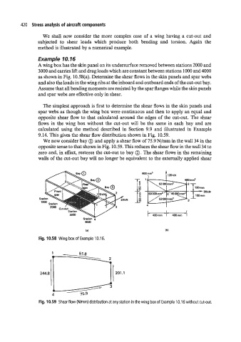
A wing box has the skin panel on its undersurface removed between stations 2000 and
3000 and carries lift and drag loads which are constant between stations 1000 and 4000
as shown in Fig. 10.58(a). Determine the shear flows in the skin panels and spar webs
and also the loads in the wing ribs at the inboard and outboard ends of the cut-out bay.
Assume that all bending moments are resisted by the spar flanges while the skin panels
and spar webs are effective only in shear.
The simplest approach is first to determine the shear flows in the skin panels and
spar webs as though the wing box were continuous and then to apply an equal and
opposite shear flow to that calculated around the edges of the cut-out. The shear
flows in the wing box without the cut-out will be the same in each bay and are
calculated using the method described in Section 9.9 and illustrated in Example
9.14. This gives the shear flow distribution shown in Fig. 10.59.
We now consider bay @ and apply a shear flow of 75.9 N/mm in the wall 34 in the
opposite sense to that shown in Fig. 10.59. This reduces the shear flow in the wall 34 to
zero and, in effect, restores the cut-out to bay 0. The shear flows in the remaining
walls of the cut-out bay will no longer be equivalent to the externally applied shear
WO mm2
120 kN
20 kN
4
- I_
mmm I mmm
Station 4
4Ooo
la1 lbl
Fig. 10.58 Wing box of Example 10.16.
Fig. 10.59 Shear flow (Wmm) distribution at any station in the wing box of Example 10.1 6 without cut-out.