
Page 441 - Aircraft Stuctures for Engineering Student
P. 441
422 Stress analysis of aircraft components
It can be seen from the magnitudes and directions of these correction shear flows (Fig.
10.60) that at any section in bay @ the loads in the upper and lower flanges of the
front spar are equal in magnitude but opposite in direction; similarly for the rear
spar. Thus, the correction shear flows in bay @ produce an identical system of
flange loads to that shown in Fig. 10.54 for the cut-out bays in the wing structure
of Example 10.15. It follows that these correction shear flows produce differential
bending of the front and rear spars in bay 0 and that the spar bending moments
and hence the flange loads are zero at the mid-bay points. Thus, at station 3000 the
flange loads are
PI = (75.9 + 53.1) x 500 = 64 500N (Compression)
P4 = 64 500 N (Tension)
Pz = (75.9 + 117.6) x 500 = 96 750 N (Tension)
P3 = 96750N (Tension)
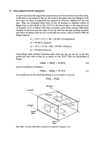
These flange loads produce correction shear flows &, d3, d3 and dl in the skin
panels and spar webs of bay @) as shown in Fig. 10.62. Thus for equilibrium of
flange 1
1OOOd1+ 1000& = 64 500 N (iii)
and for equilibrium of flange 2
1000& + lOOO& = 96750N 64
For equilibrium in the chordwise direction at any section in bay @)
80041 = 800d3
96 750 N
64 500 N
2
64 500 N
3
Station 4
4000
Fig. 10.62 Correction shear flows in bay 0 of the wing box of Example 10.16.