
Page 444 - Aircraft Stuctures for Engineering Student
P. 444
10.6 laminated composite structures 425
The shear flows q3 may be obtained by considering either vertical or horizontal
sections not containing the cut-out. Thus
q3l1 + q2lw = qavl
Substituting for q2 from Eq. (10.42) and noting that 1 = lI + 1, and d = dl + dw, we
obtain
(10.43)
.
---'
-*fiwv rc___RI "P
~~
=aminated composite s t s
An increasingly large proportion of the structures of many modern aircraft are
fabricated from composite materials. These, as we saw in Chapter 7, consist of
laminas in which a stiff, high strength filament, for example carbon fibre, is embedded
in a matrix such as epoxy, polyester etc. The use of composites can lead to consider-
able savings in weight over conventional metallic structures. They also have the
advantage that the direction of the filaments in a multi-lamina structure may be
aligned with the direction of the major loads at a particular point resulting in a
more efficient design. In this section we shall derive expressions for the elastic
constants of a composite and consider the analysis of a simple lamina subjected to
transverse and in-plane loads.
10.6.1 Elastic constants
A simple lamina of a composite structure can be considered as orthotropic with two
principal material directions in its own plane: one parallel, the other perpendicular to
the direction of the filaments; we shall designate the former the longitudinal direction
(I), the latter the transverse direction (t).
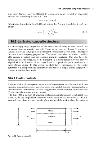
In Fig. 10.66 a portion of a lamina containing a single filament is subjected to a
stress, q, in the longitudinal direction which produces an extension Al. If it is
assumed that plane sections remain plane during deformation then the strain q
-
-
I I AI
Fig. 10.66 Determination of El.