
Page 440 - Aircraft Stuctures for Engineering Student
P. 440
10.5 Cut-outs in wings and fuselages 421
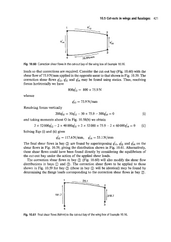
Fig. 10.60 Correction shear flows in the cut-out bay of the wing box of Example 10.16.
loads so that corrections are required. Consider the cut-out bay (Fig. 10.60) with the
shear flow of 75.9 N/mm applied in the opposite sense to that shown in Fig. 10.59. The
correction shear flows d2, d2 and d4 may be found using statics. Thus, resolving
forces horizontally we have
800d2 = 800 x 75.9N
whence
42 = 75.9N/m
Resolving forces vertically
200632 = 504'12 - 50 X 75.9 - 30044 = O (i)
and taking moments about 0 in Fig. 10.58(b) we obtain
2 x 52000& - 2 x 40000q'32 + 2 x 52000 x 75.9 - 2 x 60000qi4 = 0 (ii)
Solving Eqs (i) and (ii) gives
qi2 = 117.6N/mm, d4 = 53.1 N/mm
The final shear flows in bay @ are found by superimposing d2, qi2 and 44 on the
shear flows in Fig. 10.59, giving the distribution shown in Fig. 10.61. Alternatively,
these shear flows could have been found directly by considering the equilibrium of
the cut-out bay under the action of the applied shear loads.
The correction shear flows in bay @ (Fig. 10.60) will also modify the shear flow
distributions in bays (iJ and 0. The correction shear flows to be applied to those
shown in Fig. 10.59 for bay 0 (those in bay @ will be identical) may be found by
determining the flange loads corresponding to the correction shear flows in bay @ .
4
Fig. 10.61 Final shear flows (Wmm) in the cut-out bay of the wing box of Example 10.16.