
Page 435 - Aircraft Stuctures for Engineering Student
P. 435
416 Stress analysis of aircraft components
structure so that loads are redistributed in the vicinity of the cut-out affecting loads in
the skin, stringers, ribs and frames of the wing and fuselage. Frequently these regions
must be heavily reinforced resulting in unavoidable weight increases.
10.5.1 Cutats in wings
Initially we shall consider the case of a wing subjected to a pure torque in which one
bay of the wing has the skin on its undersurface removed. The method is best
illustrated by a numerical example.
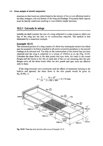
Example 10.15
The structural portion of a wing consists of a three-bay rectangular section box which
may be assumed to be hly attached at all points around its periphery to the aircraft
fuselage at its inboard end. The skin on the undersurface of the central bay has been
removed and the wing is subjected to a torque of lOkNm at its tip (Fig. 10.53).
Calculate the shear flows in the skin panels and spar webs, the loads in the corner
hges and the forces in the ribs on each side of the cut-out assuming that the spar
hges carry all the-direct loads while the skin panels and spar webs are effective
only in shear.
If the wing structure were continuous and the effects of restrained warping at the
built-in end ignored, the shear flows in the skin panels would be given by
Eq. (9.49), i.e.
T 10 x lo6
q=-- = 31.3N/m~l
2A - 2 x 200 x 800
Statio
I
Fig. 10.53 Three-bay wing structure with cut-out of Example 10.1 5.