
Page 433 - Aircraft Stuctures for Engineering Student
P. 433
414 Stress analysis of aircraft components
I
320 rnm
-
7.0 N/rnrn
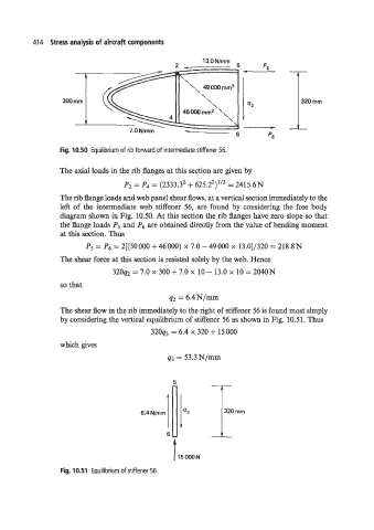
Fig. 10.50 Equilibrium of rib forward of intermediate stiffener 56.
The axial loads in the rib flanges at this section are given by
Pz = P4 = (2333.32 + 625.22)''2 = 2415.6N
The rib flange loads and web panel shear flows, at a vertical section immediately to the
left of the intermediate web stiffener 56, are found by considering the free body
diagram shown in Fig. 10.50. At this section the rib flanges have zero slope so that
the flange loads P5 and P6 are obtained directly from the value of bending moment
at this section. Thus
P5=P6=2[(50000+46000) ~7.0-49000~ 13.0]/320=218.8N
The shear force at this section is resisted solely by the web. Hence
32092 = 7.0 x 300 + 7.0 x 10 - 13.0 x 10 = 2040N
so that
42 6.4N/-
The shear flow in the rib immediately to the right of stiffener 56 is found most simply
by considering the vertical equilibrium of stiffener 56 as shown in Fig. 10.51. Thus
320q3 = 6.4 x 320 + 15000
which gives
q3 = 53.3N/mm
Fig. 10.51 Equilibrium of stiffener 56.