
Page 437 - Aircraft Stuctures for Engineering Student
P. 437
418 Stress analysis of aircraft components
4500
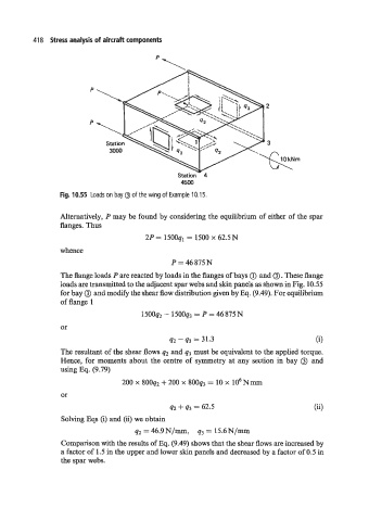
Fig. 10.55 Loads on bay @ of the wing of Example 10.15.
Alternatively, P may be found by considering the equilibrium of either of the spar
flanges. Thus
2P = 1500ql = 1500 x 62.5N
whence
P = 46875N
and
The flange loads P are reacted by loads in the flanges of bays (iJ 0. These flange
loads are transmitted to the adjacent spar webs and skin panels as shown in Fig. 10.55
for bay 0 and modify the shear flow distribution given by Eq. (9.49). For equilibrium
of flange 1
1500q2 - 150093 = P 46 875 N
or
42 - q3 = 31.3 6)
The resultant of the shear flows q2 and q3 must be equivalent to the applied torque.
Hence, for moments about the centre of symmetry at any section in bay 0 and
using Eq. (9.79)
200 x 800q2 + 200 x 800q3 = 10 x lo6 N mm
or
q2 + q3 = 62.5
Solving Eqs (i) and (ii) we obtain
92 = 46.9N/mm, 93 = 15.6N/n~n
Comparison with the results of Eq. (9.49) shows that the shear flows are increased by
a factor of 1.5 in the upper and lower skin panels and decreased by a factor of 0.5 in
the spar webs.