
Page 438 - Aircraft Stuctures for Engineering Student
P. 438
10.5 Cut-outs in wings and fuselages 419
46875N
46875 N
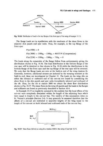
Fig. 10.56 Distribution of load in the top flange of the front spar of the wing of Example 10.1 5.
The flange loads are in equilibrium with the resultants of the shear flows in the
adjacent skin panels and spar webs. Thus, for example, in the top flange of the
front spar
P(st.4500) = 0
P(st.3000) = 1500q2 - 1500q3 = 46 875 N (Compression)
P(~t.2250) = 15ooq2 - 1500q3 - 750ql = 0
The loads along the remainder of the flange follow from antisymmetry giving the
distribution shown in Fig. 10.56. The load distribution in the bottom flange of the
rear spar will be identical to that shown in Fig. 10.56 while the distributions in the
bottom flange of the front spar and the top flange of the rear spar will be reversed.
We note that the flange loads are zero at the built-in end of the wing (station 0).
Generally, however, additional stresses are induced by the warping restraint at the
built-in end; these are investigated in Chapter 11. The loads on the wing ribs on
either the inboard or outboard end of the cut-out are found by considering the
shear flows in the skin panels and spar webs immediately inboard and outboard of
the rib. Thus, for the rib at station 3000 we obtain the shear flow distribution
shown in Fig. 10.57. The shear flows in the wing rib panels and the loads in the flanges
and stiffeners are found as previously described in Section 10.4.
In Example 10.15 we implicitly assumed in the analysis that the local effects of the
cut-out were completely dissipated within the length of the adjoining bays which
were equal in length to the cut-out bay. The validity of this assumption relies on
St. Venant’s principle (Section 2.4). It may generally be assumed therefore that the
effects of a cut-out are restricted to spanwise lengths of the wing equal to the
length of the cut-out on both inboard and outboard ends of the cut-out bay.
1
46.9
46.9
(9, -93)
- I
46.9
Fig. 10.57 Shear flows (Wmm) on wing rib at station 3000 in the wing of Example 10.1 5.