
Page 442 - Aircraft Stuctures for Engineering Student
P. 442
10.5 Cut-outs in wings and fuselages 423
271.4 142.3
4 113.9
Fig. 10.63 Final shear flows in bay @ (and bay 0) of the wing box of Example 10.16.
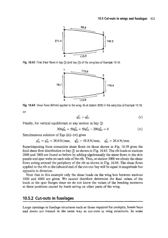
79.7
Fig. 10.64 Shear flows (Wrnm) applied to the wing rib at station 3000 in the wing box of Example 10.16.
or
d1 = d3
Finally, for vertical equilibrium at any section in bay @)
30041 + 50& + 5oq& - 200& = 0 (vi)
Simultaneous solution of Eqs (iii)-(vi) gives
qgl = d3 = 38.0N/mm, d3 = 58.8N/mm, dl = 26.6N/mm
Superimposing these correction shear flows on those shown in Fig. 10.59 gives the
final shear flow distribution in bay @) as shown in Fig. 10.63. The rib loads at stations
2000 and 3000 are found as before by adding algebraically the shear flows in the skin
panels and spar webs on each side of the rib. Thus, at station 3000 we obtain the shear
flows acting around the periphery of the rib as shown in Fig. 10.64. The shear flows
applied to the rib at the inboard end of the cut-out bay will be equal in magnitude but
opposite in direction.
Note that in this example only the shear loads on the wing box between stations
1000 and 4000 are given. We cannot therefore determine the final values of the
loads in the spar flanges since we do not know the values of the bending moments
at these positions caused by loads acting on other parts of the wing.
10.5.2 Cut-outs in fuselages
y_
Large openings in fuselage structures such as those required for cockpits, bomb bays
and doors are treated in the same way as cut-outs in wing structures. In some