
Page 436 - Aircraft Stuctures for Engineering Student
P. 436
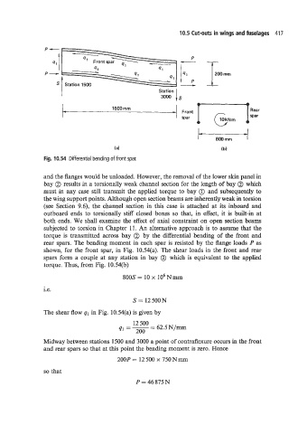
10.5 Cut-outs in wings and fuselages  417


                                                                        200 mm
                     I                                Station
                                                      3000 Is

                                      1500 rnm
                                                                          R
                                                                              e
                                                          _I  Fm;t   F  I  10 kN m   a  war  r
                                                                  w


                                       (a)                                ( b)
                Fig.  10.54  Differential bending of front spar.


               and the flanges would be unloaded. However, the removal of the lower skin panel in
                bay @ results in a torsionally weak channel section for the length of bay @ which
               must in  any case still transmit  the applied torque to bay (iJ and subsequently to
               the wing support points. Although open section beams are inherently weak in torsion
                (see Section 9.6), the  channel section in  this case is  attached  at its inboard  and
                outboard  ends to  torsionally stiff closed boxes  so that,  in  effect, it is  built-in at
                both  ends. We shall examine the effect of  axial constraint on open section beams
                subjected to torsion in Chapter  11. An alternative approach is to assume that the
               torque is  transmitted  across bay  @  by  the  differential bending of  the front  and
                rear  spars. The bending moment in each spar is resisted by  the flange loads P as
                shown, for the front spar, in Fig.  10.54(a). The shear loads in the front and rear
                spars form a  couple at any  station  in  bay  @  which is equivalent to the  applied
                torque. Thus, from Fig. 10.54(b)
                                          800s = 10 x 106Nmm

               i.e.
                                             S = 12500N

               The shear flow q1 in Fig. 10.54(a) is given by
                                             12  500
                                        41  = - 62.5 N/mm
                                                   =
                                              200
               Midway between stations 1500 and 3000 a point of contraflexure occurs in the front
                and rear spars so that at this point the bending moment is zero. Hence
                                        200P = 12 500 x 750 N lzl~ll

                so that
                                              P = 46 875N