
Page 432 - Aircraft Stuctures for Engineering Student
P. 432
10.4 Fuselage frames and wing ribs 413
300 rnrn 300 mrn
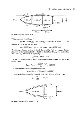
Fig. 10.48 Wing rib of Example 10.14.
Taking moments about flange 3
2(50000+95000)q23 +2 x 95000q12 = -15000 x 300Nmm (iii)
Solution of Eqs (i), (ii) and (iii) gives
q12 = 13.0N/~, q23 = -7.ON/m, 431 = 43.0N/m
Consider now the nose portion of the rib shown in Fig. 10.49 and suppose that the
shear flow in the web immediately to the left of the stiffener 24 is ql. The total vertical
shear force Sy,l at this section is given by
Sy,l = 7.0 x 300 = 2100N
The horizontal components of the rib flange loads resist the bending moment at this
section. Thus
2 x 50 000 x 7.0 = 2333.3
px,4 = px,2 = 300
The corresponding vertical components are then
Py,2 = Py,4 = 2333.3 tan 15" = 625.2N
Thus the shear force carried by the web is 2100 - 2 x 625.2 = 849.6N. Hence
849.6
41 =-=2.8N/m
300
- 4'
py.4 p4
Fig. 10.49 Equilibrium of nose portion of the rib.