
Page 425 - Aircraft Stuctures for Engineering Student
P. 425
406 Stress analysis of aircraft components
Aircraft are constructed primarily from thin metal skins which are capable of resisting
in-plane tension and shear loads but buckle under comparatively low values of in-
plane compressive loads. The skins are therefore stiffened by longitudinal stringers
which. resist the in-plane compressive loads and, at the same time, resist small
distributed loads normal to the plane of the skin. The effective length in compression
of the stringers is reduced, in the case of fuselages, by transverse frames or bulkheads
or, in the case of wings, by ribs. In addition, the frames and ribs resist concentrated
loads in transverse planes and transmit them to the stringers and the plane of the skin.
Thus, cantilever wings may be bolted to fuselage frames at the spar caps while under-
carriage loads are transmitted to the wing through spar and rib attachment points.
Generally, frames and ribs are themselves fabricated from thin sheets of metal and
therefore require stiffening members to distribute the concentrated loads to the thin
webs. If the load is applied in the plane of a web the stiffeners must be aligned with
the direction of the load. Alternatively, if this is not possible, the load should be
applied at the intersection of two stiffeners so that each stiffener resists the component
of load in its direction. The basic principles of stiffener/web construction are
illustrated in Example 10.13.
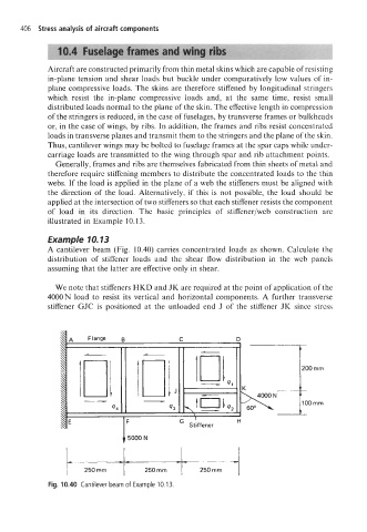
Example 10.13
A cantilever beam (Fig. 10.40) carries concentrated loads as shown. Calculate the
distribution of stiffener loads and the shear flow distribution in the web panels
assuming that the latter are effective only in shear.
We note that stiffeners HKD and JK are required at the point of application of the
4000 N load to resist its vertical and horizontal components. A further transverse
stiffener GJC is positioned at the unloaded end J of the stiffener JK since stress
rnrn
rnrn
* -- - __ t
250 rnrn 250 rnrn 250 rnm