Page 417 - Aircraft Stuctures for Engineering Student
P. 417
398  Stress analysis of aircraft components

                   The actual shear flows are obtained by factoring the final shear flows by the ratio of
                   the applied torque to the torque corresponding to the final shear flows, Le.


                   Example 10.10
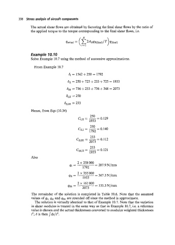
                   Solve Example 10.7 using the method of successive approximations.

                     From Example 10.7
                                          61 = 1542 + 250 = 1792

                                         611 = 250 + 725 + 233 + 725 = 1933

                                        6111 = 736 + 233 + 736 + 368 = 2073
                                        61,~ = 250

                                       611,111  = 233

                   Hence, from Eqs (10.34)
                                                      250
                                               CI,II = - 0.129
                                                          =
                                                      1933
                                                      250
                                               CII!J = - 0.140
                                                          =
                                                      1792
                                                      233
                                              C,,,J,, = - 0.1 12
                                                          =
                                                      2073
                                                      233
                                              CII1,II = - 0.121
                                                          =
                                                      1933
                   Also
                                                  258000 = 287.9N/mm
                                          ‘I  =   1792
                                                  355 Oo0  = 367.3 N/mm
                                          ‘I1  =   1933


                    The remainder of the solution is completed in Table 10.6. Note that the assumed
                    values of qI, qII and qIII are rounded off since the method is approximate.
                      The solution is virtually identical to that of Example 10.7. Note that the variation
                    in shear modulus is treated in the same way as that in Example 10.7, i.e. a reference
                    value is chosen and the actual thicknesses converted to modulus weighted thicknesses
                    t*; 6 is then Jds/t*.

