
Page 414 - Aircraft Stuctures for Engineering Student
P. 414
10.3 Wings 395
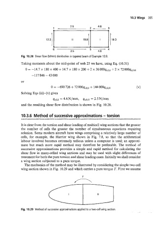
2.5 4.6
1 2
12.2
6 - 4.6 - 4
2.5
Fig. 10.28 Shear flow (Wmm) distribution in tapered beam of Example 10.9.
Taking moments about the mid-point of web 25 we have, using Eq. (10.31)
0 = -14.7 x 180 x 400 + 14.7 x 180 x 200 + 2 x 36000q,:031 + 2 X 72oooq,,0.~1
-117846-43680
or
0 = -690 726 + 72000q,,o,~ + 144OOOq,,o,I~
Solving Eqs (iii)-(v) gives
qs,o.r = 4.6 N/m7 4S,O,II = 2.5 N/mm
and the resulting shear flow distribution is shown in Fig. 10.28.
10.3.6 Method of successive approximations - torsion
It is clear from the torsion and shear loading of multicell wing sections that the greater
the number of cells the greater the number of simultaneous equations requiring
solution. Some modem aircraft have wings comprising a relatively large number of
cells, for example, the Harrier wing shown in Fig. 7.8, so that the arithmetical
labour involved becomes extremely tedious unless a computer is used; an approxi-
mate but much more rapid method may therefore be preferable. The method of
successive approximations provides a simple and rapid method for calculating the
shear flow in many-celled wing sections and may be used with slight differences of
treatment for both the pure torsion and shear loading cases. Initially we shall consider
a wing section subjected to a pure torque.
The mechanics of the method may be illustrated by considering the simple two-cell
wing section shown in Fig. 10.29 and which carries a pure torque T. First we assume
Fig. 10.29 Method of successive approximations applied to a two-cell wing section.