
Page 514 - Aircraft Stuctures for Engineering Student
P. 514
12.1 Notation 495
idealization of what are known as ‘skeletal’ structures. Such structures are assumed to
consist of a number of elements joined at points called nodes. The behaviour of each
element may be determined by basic methods of structural analysis and hence the
behaviour of the complete structure is obtained by superposition. Operations such
as this are easily carried out by matrix methods as we shall see later in this chapter.
A more difficult type of structure to idealize is the continuum structure; in this
category are dams, plates, shells and, obviously, aircraft fuselage and wing skins. A
method, extending the matrix technique for skeletal structures, of representing con-
tinua by any desired number of elements connected at their nodes was developed
by Clough et aL2 at the Boeing Aircraft Company and the University of Berkeley
in California. The elements may be of any desired shape but the simplest, used in
plane stress problems, are the triangular and quadrilateral elements. We shall discuss
thefinite element method, as it is known, in greater detail later.
Initially, we shall develop the matrix stiffness method of solution for simple skeletal
and beam structures. The fundamentals of matrix algebra are assumed.
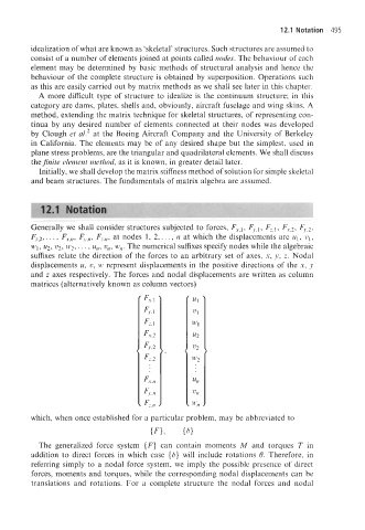
Generally we shall consider structures subjected to forces, Fr,l, Fy,l, Fz,l, Fy,2, F,.,2,
Fr,2,. . . , F,.+ Fy,,, F,,,, at nodes 1, 2,. . ., n at which the displacements are ul, VI,
wl, u2, u2, w2,. . . , u,, u,, w,. The numerical suffixes specify nodes while the algebraic
suffixes relate the direction of the forces to an arbitrary set of axes, x, y, z. Nodal
displacements u, u, w represent displacements in the positive directions of the x, y
and z axes respectively. The forces and nodal displacements are written as column
matrices (alternatively known as column vectors)
which, when once -established for a particular problem, may be abbreviated to
{F), (6)
The generalized force system {F} can contain moments M and torques T in
addition to direct forces in which case (6) will include rotations 6. Therefore, in
referring simply to a nodal force system, we imply the possible presence of direct
forces, moments and torques, while the corresponding nodal displacements can be
translations and rotations. For a complete structure the nodal forces and nodal