Page 518 - Aircraft Stuctures for Engineering Student
P. 518
12.3 Stiffness matrix for two elastic springs in line  499

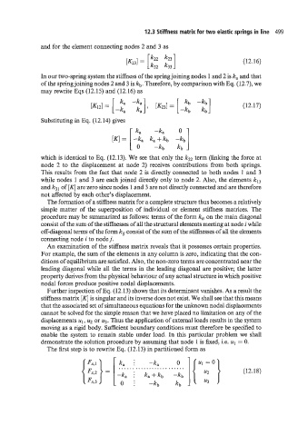
              and for the element connecting nodes 2 and 3 as

                                                                                (12.16)

              In our two-spring system the stiffness of the spring joining nodes 1 and 2 is ka and that
              of the spring joining nodes 2 and 3 is kb. Therefore, by comparison with Eq. (12.7), we
              may rewrite Eqs (12.15) and (12.16) as

                                                                                (12.17)

              Substituting in Eq. (12.14) gives
                                             ka    -ka     0
                                      [K] =  -ka   ka+kb  -kb]
                                           [ 0     -kb     kb
              which is identical to Eq. (12.13). We see that only the kZ2 term (linking the force at
              node  2 to the  displacement at node  2) receives contributions  from  both  springs.
              This results from the fact that node 2 is directly connected to both nodes 1 and 3
              while nodes 1 and 3 are each joined directly only to node 2. Also, the elements kI3
              and k31 of [K] are zero since nodes 1 and 3 are not directly connected and are therefore
              not affected by each other’s displacement.
                The formation of a stiffness matrix for a complete structure thus becomes a relatively
              simple matter  of  the  superposition of individual or element stiffness matrices. The
              procedure may be summarized as follows: terms of the form kii on the main diagonal
              consist of the sum of the stiffnesses of all the structural elements meeting at node i while
              off-diagonal terms of the form kii consist of the sum of the stiffnesses of all the elements
              connecting node i to node j.
                An examination of the stiffness matrix reveals that it possesses certain properties.
              For example, the sum of the elements in any column is zero, indicating that the con-
              ditions of equilibrium are satisfied. Also, the non-zero terms are concentrated near the
              leading diagonal while all the terms in the leading diagonal are positive; the latter
              property derives from the physical behaviour of any actual structure in which positive
              nodal forces produce positive nodal displacements.
                Further inspection of Eq. (12.13) shows that its determinant vanishes. As a result the
              stiffness matrix [K] is singular and its inverse does not exist. We shall see that this means
              that the associated set of simultaneous equations for the unknown nodal displacements
              cannot be solved for the simple reason that we have placed no limitation on any of the
              displacements  141 , y or u3. Thus the application of external loads results in the system
              moving as a rigid body. Sufficient boundary conditions must therefore be specified to
              enable the system to remain stable under load. In this particular problem we  shall
              demonstrate the solution procedure by assuming that node 1 is fixed, i.e. u1  = 0.
                The first step is to rewrite Eq. (12.13) in partitioned form as


                                        .o. ..; ............ ......
                                   =                                            (12.18)
                                       -ka  i   ka +kb

