Page 521 - Aircraft Stuctures for Engineering Student
P. 521
502  Matrix methods of structural analysis

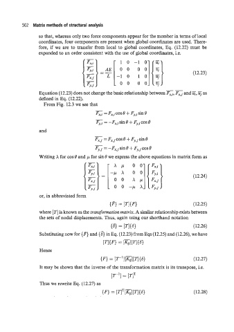
                  so that, whereas only two force components appear for the member in terms of local
                  coordinates, four components are present when global coordinates are used. There-
                  fore, if  we  are to  transfer from local to global coordinates, Eq.  (12.22) must  be
                  expanded to an order consistent with the use of global coordinates, i.e.


                                                                        --
                  Equation (12.23) does not change the basic relationship between Fx,i, Fx,j and i&  as
                  defined in Eq. (12.22).
                    From Fig. 12.3 we see that
                                          -
                                          Fx,i = Fx,i cos 8 + Fy,i sin 8
                                             = -Fx:i sin 8 + Fy,i cos 8
                  and
                                          -
                                          Fx,j =FxJcos8+ FY;,,sin8
                                          -
                                          Fy,j =-Fx,jsin8+  Fy,jcos8
                  Writing X for cos 8 an  ,u for sin 8 we express the above equations in matrix form as
                                                     I    B


                                                -k 00-pX :]{;y,j,


                  or, in abbreviated form
                                                IF1 = [mF}                          (12.25)
                  where [TI is known as the transformation matrix. A similar relationship exists between
                  the sets of nodal displacements. Thus, again using our shorthand notation
                                                    = [TI{S}                        (12.26)
                  Substituting now for {F} and {J} in Eq. (12.23) from Eqs (12.25) and (12.26), we have
                                             [TI{F} = [K,l[~I{S}
                  Hence
                                            {F} = [T-'l[K,l[Tl{S}                   (12.27)

                  It may be shown that the inverse of the transformation matrix is its transpose, i.e.
                                                 [T-'] = [TIT
                  Thus we rewrite Eq. (12.27) as
                                             {Fl= [TITm[7-l{s>                      (12.28)

