Page 522 - Aircraft Stuctures for Engineering Student
P. 522
12.4 Matrix analysis of pin-jointed frameworks  503

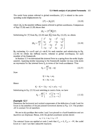
               The nodal force system referred to global coordinates, {F} is related to the corre-
               sponding nodal displacements by

                                             if7 = [Ki,{S)                       (12.29)
               where [ICi,.] is the member stiffness matrix referred to global coordinates. Comparison
               of Eqs (12.28) and (12.29) shows that
                                           [Kg1 = [TlTrn[T1

               Substituting for [TI from Eq. (12.24) and [K,] from Eq. (12.23), we obtain


                                                                                 (12.30)


               By  evaluating A(=  cos@) and p(=  sine) for each member and substituting in Eq.
               (12.30) we  obtain  the  stiffness matrix,  referred  to  global  coordinates,  for  each
               member of the framework.
                 In Section 12.3 we determined the internal force in a spring from the nodal displa-
               cements. Applying similar reasoning to the framework member we may write down
               an expression for the internal force SU in terms of the local coordinates. Thus
                                                                                 (12.31)

               Now
                                             -
                                             tlj  = xuj + pvj
                                             -
                                             ui = XUf + pvj
               Hence
                                     -
                                     uj  -  = X(Uj  - ui) + p(vj - Wi)
               Substituting in Eq. (12.31) and rewriting in matrix form, we have


                                                                                 (12.32)

               Example 12.1
               Determine the horizontal and vertical components of the deflection of node 2 and the
               forces in the members of the pin-jointed framework shown in Fig. 12.4. The product
               AE is constant for all members.

                 We see in this problem that nodes 1 and 3 are pinned to a hed foundation and are
               therefore not displaced. Hence, with the global coordinate system shown
                                          u1 = 211  = u3 = v3 = 0
               The external forces are applied at node 2 such that FX,2 = 0, FY,~ = - W; the nodal
               forces at 1 and 3 are then unknown reactions.

