
Page 523 - Aircraft Stuctures for Engineering Student
P. 523
504 Matrix methods of structural analysis
t’
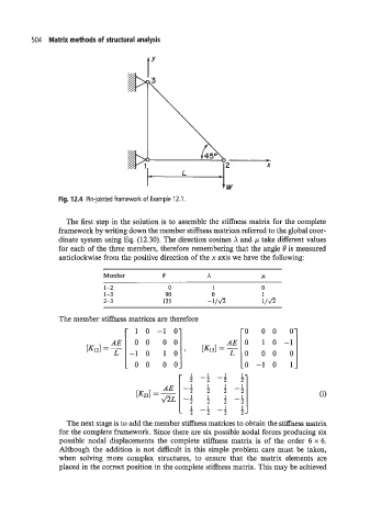
Fig. 12.4 Pin-jointed framework of Example 12.1.
The first step in the solution is to assemble the stiffness matrix for the complete
framework by writing down the member stiffness matrices referred to the global coor-
dinate system using Eq. (12.30). The direction cosines X and p take different values
for each of the three members, therefore remembering that the angle is measured
anticlockwise from the positive direction of the x axis we have the following:
Member 0 x P
1-2 0 1 0
1-3 90 0 1
2-3 135 -l/& l/&
The member stiffness matrices are therefore
10-10 0 00 0
00 0
0-10 1
The next stage is to add the member stiffness matrices to obtain the stiffness matrix
for the complete framework. Since there are six possible nodal forces producing six
possible nodal displacements the complete stiffness matrix is of the order 6 x 6.
Although the addition is not difficult in this simple problem care must be taken,
when solving more complex structures, to ensure that the matrix elements are
placed in the correct position in the complete stiffness matrix. This may be achieved