
Page 524 - Aircraft Stuctures for Engineering Student
P. 524
12.4 Matrix analysis of pin-jointed frameworks 505
by expanding each member stiffness matrix to the order of the complete stiffness
matrix by inserting appropriate rows and columns of zeros. Such a method is, how-
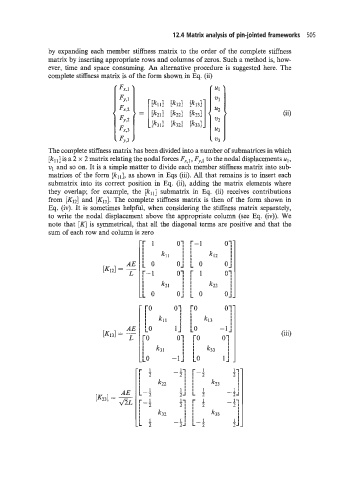
ever, time and space consuming. An alternative procedure is suggested here. The
complete stiffness matrix is of the form shown in Eq. (ii)
(ii)
The complete stiffness matrix has been divided into a number of submatrices in which
[kI1] is a 2 x 2 matrix relating the nodal forces cy,l, F5.,] to the nodal displacements ul,
v1 and so on. It is a simple matter to divide each member stiffness matrix into sub-
matrices of the form [kll;, as shown in Eqs (iii). All that remains is to insert each
submatrix into its correct position in Eq. (ii), adding the matrix elements where
they overlap; for example, the [kllj submatrix in Eq. (ii) receives contributions
from [K12] and [KI3]. The complete stiffness matrix is then of the form shown in
Eq. (iv). It is sometimes helpful, when considering the stiffness matrix separately,
to write the nodal displacement above the appropriate column (see Eq. (iv)). We
note that [K] is symmetrical, that all the diagonal terms are positive and that the
sum of each row and column is zero
(iii)
-[ 4 -Li r-l Ll
2; ;
21
2
k22 I I 1 I I k73 I
I
I 1 11 I 1 1:
L-2 2J L 5 - 2-I
[-; 1-1 r 1 - 11
11
2
2;
-1
I I I
k32 I I k33 I
I 1 1: I 1 1I
-L 3 -2-I L-2 ZJ